Setting up the Compressed Spectral Array (CSA)
Step by Step Guide
- Collect all required equipment (EEG module and lead, 5 ECG electrodes, Clinell skin wipe).

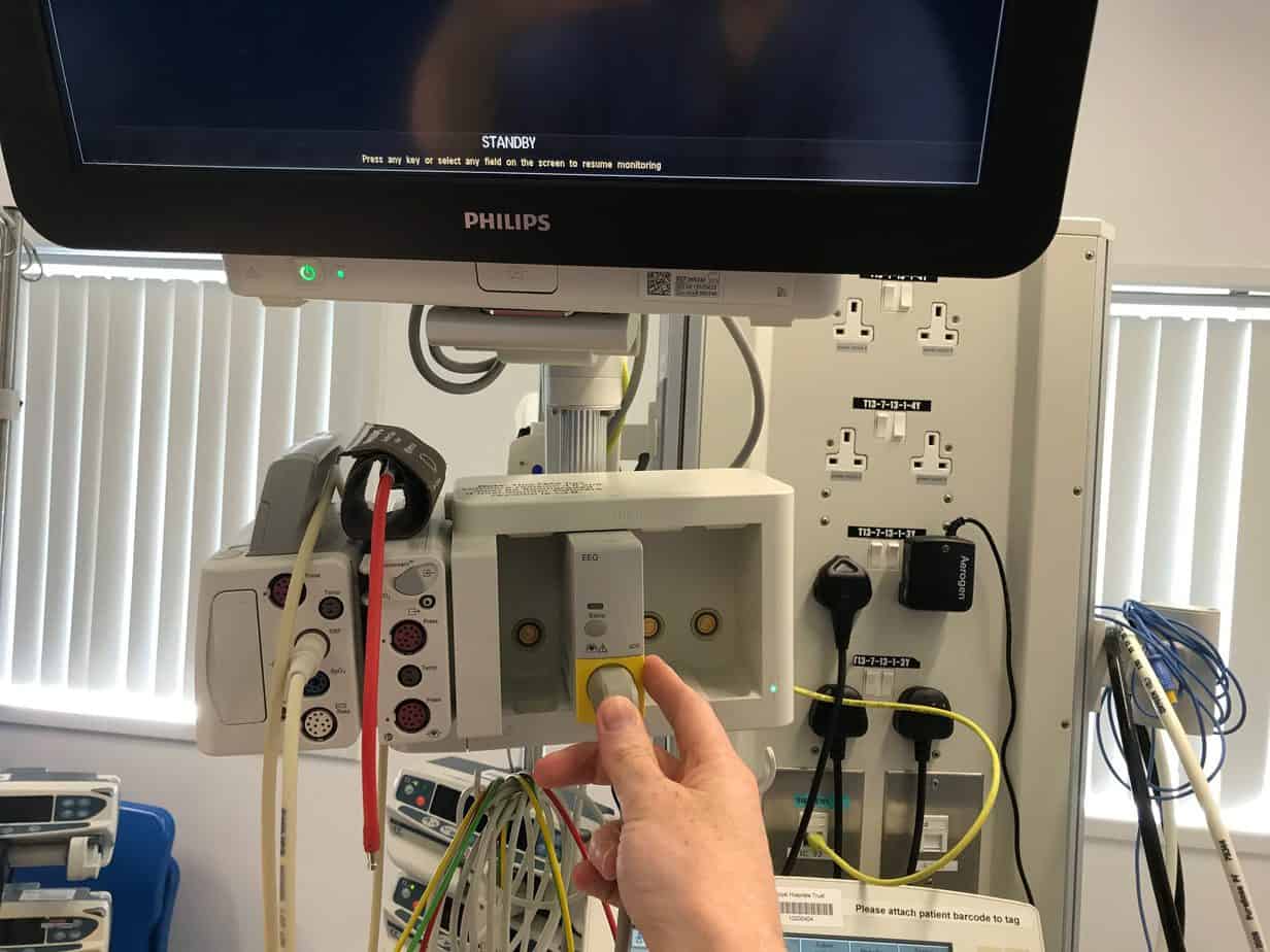
2. Inserted the EEG module and cable into the module rack.
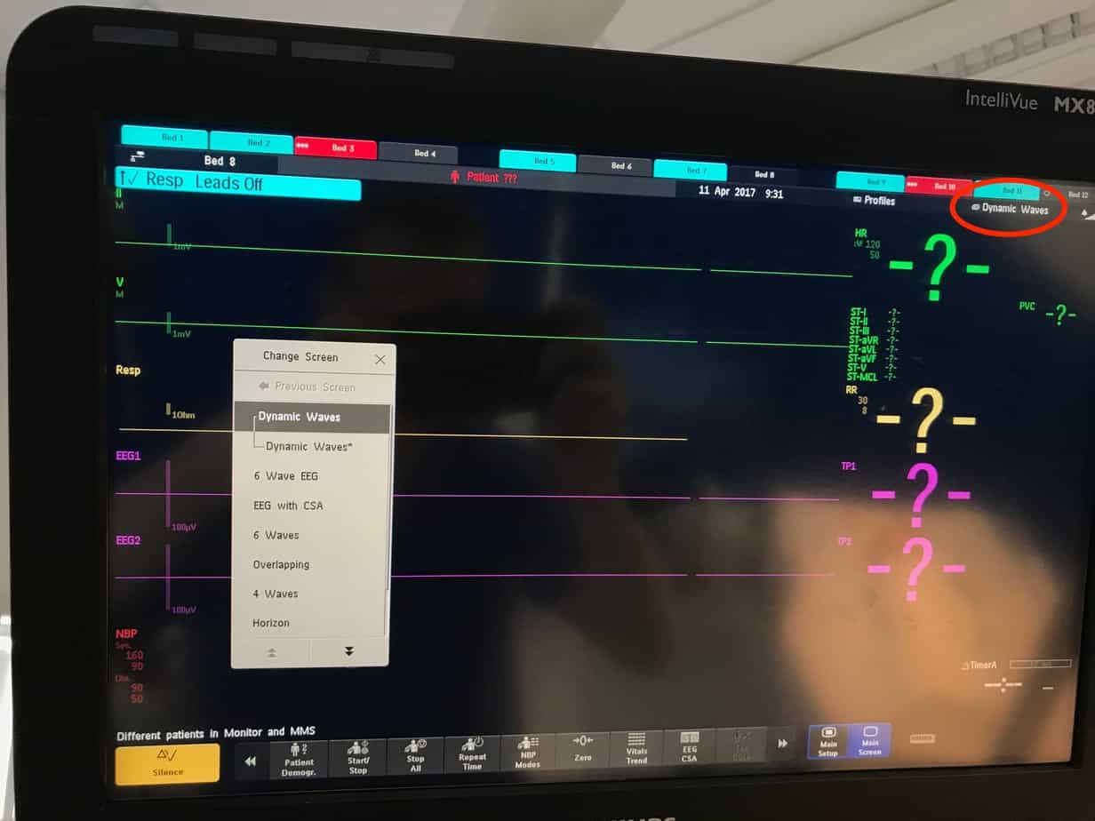
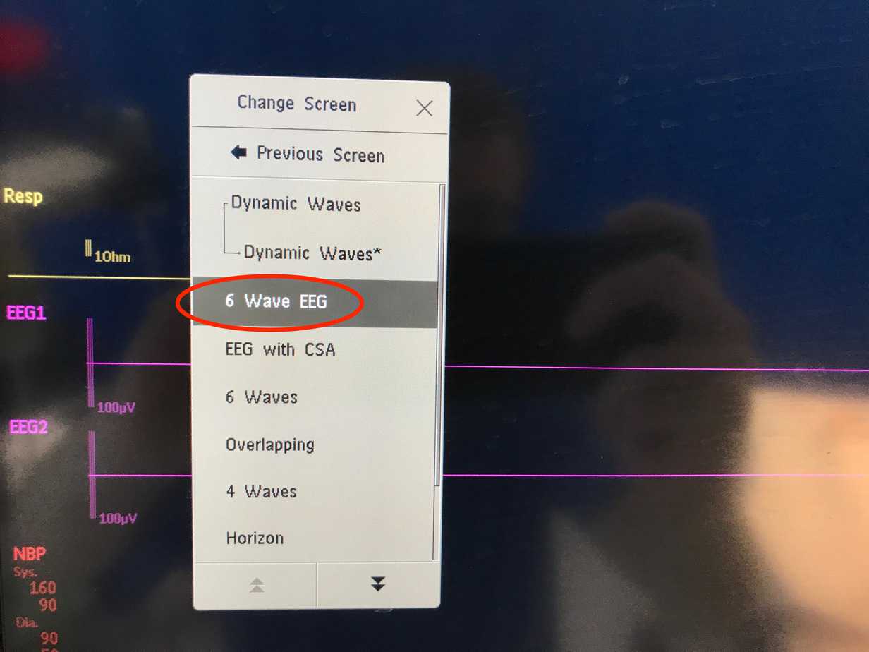
3. Click the currently selected monitoring screen from the top right hand corner and change to ‘6 wave EEG’. Don’t select ‘EEG with CSA’ as this doesn’t leave enough room for all the other dynamic waves required in most intensive care patients.
4. Click on the icon in the bottom right hand corner of the screen to open the measurement selection.

5. Click on ‘EEG’ and and then ‘Setup EEG’ from the menu that appears at the bottom.

6. Select ‘Show Montage’ from the Setup EEG menu.

The EEG Montage will then be displayed on the screen and can be used to help confirm correct location when applying the electrodes. Montage A is used by default. This can be changed from the pull down menu if required e.g. you are unable to place the electrodes in the specified positions.

7. Clean the skin over forehead and temporal region with a clinell skin wipe and allow to dry.

8. Attach the reference electrode to the middle of the patient’s forehead and plug into the reference slot (middle space) on the EEG cable.

9. Attach the Fp1 electrode to the left hand side of the patient’s forehead and plug into the EEG1+ slot (far left space) on the EEG cable.

10. Attach the Fp2 electrode to the right hand side of the patient’s forehead and plug into the EEG2+ slot (far right space) on the EEG cable.

11. Attach the T3 electrode to the left temporal region and plug into the EEG1- slot (2nd from the left space) on the EEG cable.

12. Attach the T4 electrode to the right temporal region and plug into the EEG2 – slot (2nd from the right space) on the EEG cable.

As you attach the electrodes the the icon on the montage will initially change from a ‘red x’ to a ‘white ?’. This can be used to help ensure you have put the lead in the correct location.

As more electrodes are added the symbol on the montage will either change to an ‘amber arrow’ (indicating that the impedance is above the set limit) or a ‘green tick’ (indicating that the impedance is below the set limit). The default set impedance limit is set to 5kOhm and the current impedance for each electrode is shown at the bottom right hand corner of the montage.

13. If possible the impedance for each of the electrodes should be less than 10 kOhm. If it is more than this ensure that the electrode is well adhered to the skin. If not consider cleaning the skin again, changing the electrodes or using tape to secure the electrodes to the skin. While ideally the impedance levels should be ≤10 kOhm, if this can not be achieved the CSA will still work with values up to 40 kOhm. The impedance limit should then be adjusted so that it is just above (e.g. 5 kOhm) the highest impedance value by using the ‘ImpLimit Down’ and “ImpLimit Up’ buttons at the bottom of the screen.
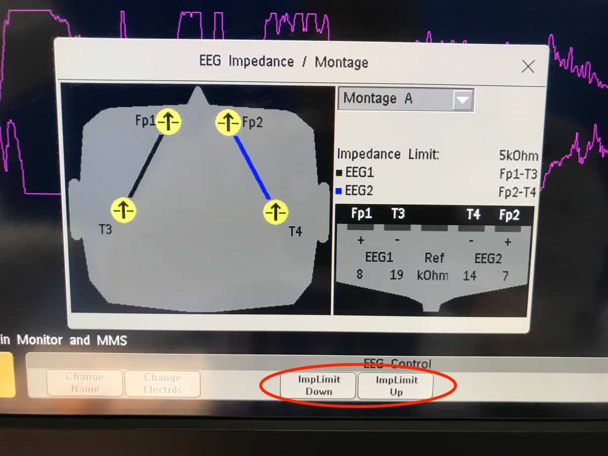
Once all the impedance values are below the set limit the icon will turn to a green tick.

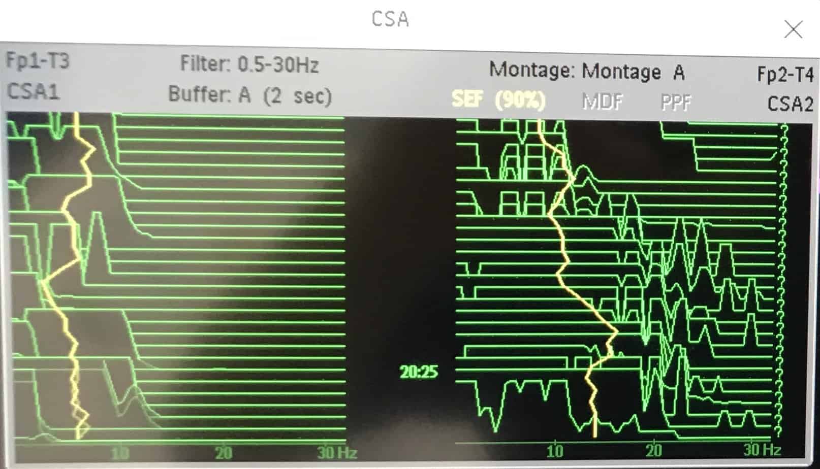
14. Close the montage screen by clicking on the X in the top right hand corner. The raw EEG will now be displayed together with the values for SEF1, SEF2, TP1 and TP2. To get the CSA to be displayed on the screen the ‘EEG CSA’ button at the bottom of the screen should be clicked.

15. The CSA will then appear and can be dragged into the desired position on the screen. If another menu on the monitor is accessed the CSA screen will disappear and will needed to be added to the main screen again by clicking on the ‘EEG CSA’ button at the bottom of the screen.

16. To adjust the settings click on the icon in the bottom right hand corner of the screen to open the measurement selection.

17. Click on ‘EEG’ and and then ‘Setup EEG’ from the menu that appears at the bottom.

The ‘Setup EEG’ menu will appear allowing you to customise the CSA display. By default only TP and SEF are displayed, however other options can be turned on from this menu if required.


18. To print a screenshot click on the ‘Print Report’ button in the bottom left hand corner. If successful a message ‘Printing to Database’ will appear and a report will print to the printer in the equipment store.

An example of a report is shown below

19. If at any stage one of the electrodes becomes loose the impedance value will exceed the set limit and the trace on the CSA will disappear and the values for SEF1 and TP will be replaced with a ‘?’. If this happens the montage should be brought up using the steps above to identify the electrode causing the problem and it should be reapplied.

![]()
